Showing posts with label 1.5V CIRCUITS. Show all posts

0 LED light "Phototheraphy" Project


While doing a research across the web, I notice the topic about phototherapy. It says that exposure to a light at specific wavelength is beneficial to human body. This light may come from various sources such as sunlight, lasers, lamps and Light Emitting Diodes (LED). According to some studies (just read more about this on the web), that exposure to light can cure some skin disease, wound healing, hair growth, and many more.
In relation to that phototherapy idea using LED, the simple circuit below is a led driver powered by a single 1.2V or 1.5V cell. Since the voltage from a single cell is not enough to light up the LED, The circuit steps up the voltage that is enough to light up the LED (see more about the forward voltage in LED info). The circuit is basically the same with the LED joule thief  in terms on how it works, but of course with different parts.
You can use this circuit for your phototherapy session and you can direct its light to your ears, nasal airways, and other parts.
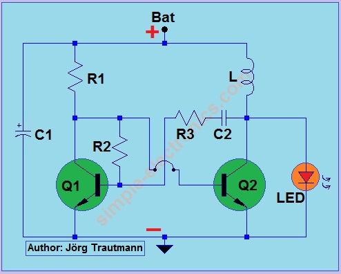

led driver schematic

Part List:
R1, R3 - 1.2 kilo ohms 1/4W
R2 - 2 kilo ohms 1/4W
C1 - 47uF electrolytic capacitor rated 3V
C2 - 470pF ceramic capacitor
L - 470uH inductor
LED - red or any low power LED (visit LED pinout in case you forgot)
Q1, Q2 - 2N2222, 9013 or similar NPN transistor

Note: There are lots of studies about this therapy but the circuit presented above has no approved therapeutic claims.

0 1.5V LED Flasher using Transistor

Another LED flasher, but this time powered only by 1.5V (take note that the minimum voltage to light up LED is 1.8V or higher). Q1 and Q2 will start to generate pulses that charge the C2. When C2 is charged, the voltage across the LED is around 1.5V plus the charge in the capacitor. This voltage is enough to light up the LED.
2N4403 pins
2N2222, 9013 pins
Part List:
R1 - 1.2 Mega ohms 1/4W
R2 - 1.2 kilo ohms 1/4W
R3, R4 - 390 ohms 1/4W
Q1, Q3 - 2N2222 or CS9013 NPN transistor
Q2  - 2N4403 or  similar PNP transistor
C1 - 1uF electrolytic capacitor
C2 - 220uF electrolytic capacitor
LED - red (see LED pinout or LED info)

Other LED Flasher Circuit:
Two transistor Flasher - two LEDs flasher
Flasher by 555 - bright flasher uses 20 or more LEDs
Fading LED - fading effect of two LED

0 Simple Hearing Aid

Hearing aid circuit powered by 1.5V battery. The circuit is a simple audio amplifier that pick up sounds then amplifies it to the headphone (Spk).
Part List :
R1 - 3.3 kilo ohms 1/4W
R2 - 120 kilo ohms 1/4W
R3 - 180 kilo ohms 1/4W
R4 - 10 kilo ohms 1/4W
R5 - 4.7 ohms 1/4W
Q1, Q2 - 2N2222 or similar NPN transistor
Q3 - 2N3906 or similar PNP transistor
C1 - 2.2uF electrolytic capacitor
C2 - 4.7uF electrolytic capacitor
Mic - electret microphone
Spk - headphone 8ohms up to 32 ohms
Bat - 1.5V battery
2N3906 pins
2N2222 pins


7 Light Activated led driver (1.5V joule thief)

This is another LED driver circuit powered by joule thief circuitry using 1.5V cell. The only difference is it has light detection that automatically turns on the led when the environment is dark.
schematic diagram

Part list:
R1 – any light dependent resistor (LDR) or photoresistor
R2 - 100 kilo ohms potentiometer
R3 – 220 ohms 1/4W
R4 - 120 kilo ohms 1/4W
R5 - 2 kilo ohms 1/4W
Q1 - 9012, 2N4403, or any similar PNP transistor
Q2, Q3 - 2N2222, 9013, or any similar NPN transistor
C - 22pF to 47pF capacitor
L - any 100uH to 1mH inductor
LED - any type of LED  (see LED pinout in case you forgot)


Part list diagrams: Click to diagrams to enlarge
PNP transistor pins
NPN transistor pins
LDR

You can adjust sensitivity of the light detector by varying the value of potentiometer R2. Full value of R2 means highest sensitivity.

Note:  see Sir Acme Fixer recommendation on how to construct the joule thief in the comments section below.

2 1.5V power supply


Wall clocks, mp3 players, electronic sensors, and special devices use 1.5V battery (cell) as power source. We sometimes forgot to buy or replace the battery but no worries because we can design circuits that can convert higher DC voltages to useable 1.5V.

The following electronic circuits are possible schematic of 1.5V power sources or regulators.

Simple 1.5V power supply
Around 20mA maximum output  current, good in low power application like wall clocks.
simple power supply
Part List:
R- 220 ohms 1/4W
D - 1N4001 or similar diode
LED - 3mm or 5mm red LED
C - 4.7uF electrolytic capacitor
DC - 4V to 6V DC source

Improved 1.5v power supply
Transistor Q increase the maximum output current up to 200mA
Improvised power supply
Part List:
R- 220 ohms 1/4W
LED - 3mm or 5mm red LED
C - 4.7uF electrolytic capacitor
Q - 2N2222, 9013 or similar NPN transistor
DC - 4V to 5V DC source

Using LM317 regulator
Output current is up to 1000mA (can be higher) and input voltage is 4V to 15V DC.  Best voltage regulation and efficiency compared to previous  power supplies. Output voltage is based on the values of R1 and R2 (see LM317 calculator for possible R1 and R2 combinations).
LM317 power supply

Part List:
R1 - 200 ohms 1/4W
R2 - 40 ohms (39 ohms) 1/4W
C - 4.7uF electrolytic capacitor
LM317 regualtor IC
DC - 4V to 12V DC source

4 1.5V led using 555 IC

This LED circuit is powered only by 1.5V cell using the 555 IC. The timer IC is operated in astable mode similar to voltage double circuit, where 1.5V is step up to around 2.5V. The circuit frequency is around 60Hz  and consumes very small power thus leaving it on is not a problem.
1.5V led circuit
Part List:

R1- 39 kilo-ohms
R2- 100 kilo-ohms
R3-10 ohms but if no light  or very dim, just short it
C1- 100nF
C2- 10nF
C3- 220uF electrolytic capacitor
C4- 100uF electrolytic capacitor
D1- preferably  schotky diode but ordinary diode like 1N4001 will do
555- use the CMOS type 555
LED- red, yellow and other low power led (do not use white or blue)
1.5V- any 1.5V battery

Note: You can use  555 timer calculator if you plan to change the frequency of the circuit.

1 1.5V LED driver using transistor

1.5V cell cannot light up led since it requires around 1.8V to 3.8V as forward voltage. This simple circuit will help us drive  LED using only 1.5V or even 1.2V cell.

Part List:
1-1.5V cell
1-1N4007 or any similar diode
1-2N2222 transistor or any similar NPN transistor
1-1.2k-ohms  resistor
1-220-ohms resistor
1-white LED or any bright LED
    *see LED pinout if you are not sure with LED pins

Circuit schematic and parts:
LED driver schematic
Ferrite core and transistor pins
Winding the  coil and making the ciruit :
First  look for any magnetic core for your coil. Toroidal ferrite core from old cfl is recommended (see diagram above) but still you can use any magnetic core available at hand. Using #22AWG magnetic wire wind it 30 turns and mark the starting as 1, center-tap as 2 and ending of the winding as number 3. Follow the led driver schematic above and its done.

Note: You can remove diode 1N4007 and 220 resistor and replace it with another LED. Their main purpose is mainly for suppressing excessive voltage that can damage the LED. Another similar and much better driver is the light activated led driver (joule thief) which is also powered by 1.5V cell.


7 Simple FM transmitter powered by 1.5V battery

This simple  FM (frequency modulation) transmitter is powered only by a 1.5V battery and uses only 1 transistor.The frequency of this transmitter is controlled by the L-C resonance circuit and operates from 80 to 110 MHz.
simple FM transmitter schematic
The inductor L1 is made of 8 turns of  #22AWG magnetic wire wound  with the diameter of 4-5cm or diameter of a pencil. The antenna is a 6 inches copper wire connected at the middle of L1 inductor. Other parts
are not critical and can be replaced by its closest value. Resistor are 1/4 watt type and capacitors are ceramic except  the 10uF electrolytic  capacitor. 5-60pF capacitor is a trimmer type or variable type.

Note: Modifying this simple fm transmitter circuit such as increasing its power capacity is illegal.Review the fcc limits regarding fm transmitter if you are planning to build a more powerful one.

Notes by Acme Fixer:(Thanks!!)
1. Add 0.01uF capacitor across 1.5V supply near the transistor.
2. You can remove the antenna.
3. Mic is an electret condenser microphone type.
4. See the rest of his recommendation based on his experience in building the circuit. See comment section below.

10 cell phone charger using 1.5V battery

Have you ever experienced going to other place and suddenly your cell phone turn off, and no power is available for you to charge your phone? Then try building this portable and emergency cell phone charger powered by 1.5V battery.


Charging your cell phone by 1.5V battery, how? 


For the cell phone to charge, charger output must be above 4V and can deliver a maximum current of 500mA. This charger circuit will step up the voltage from 1.5V to 5V DC to reach the cell phone charging requirement. The circuit uses only an AA or AAA 1.5v battery (1V to 2.4V).  The charger is composed of simple oscillator, a rectifier, and voltage regulator. The feedback winding F is composed 5 turns of #30 AWG magnetic wire and main winding P is composed of 6 turns of #24 AWG wire. The 5.1V zener diode and 2200uF capacitor regulates the output voltage to ensure proper charging.

The windings are not critical, you can experiment using different number of turns. If ever the charger doesn’t have any output, try to reverse the winding connection.

Note: This charger is functional but provides no warranty on its accuracy. Try building at your own risk.

2 1.5V LED flasher by 555 timer IC

1.5V led flasher schematic


1.5V LED flasher by 555 timer IC
Part list:
R1- 5 kilo-ohms
R2- 5 kilo-ohms
C1- 100uF electrolytic capacitor
C2- 100nF
C3- 220uF electrolytic capacitor
C4- 47uF electrolytic capacitor
D- schotky or germanium diode but ordinary diode will do (1N4001)
LED- low power red, yellow or green LED

This simple LED flasher is powered by a CMOS type 555 timer IC that performs as a voltage doubler circuit to power up an LED. This 555 timer is operated in astable mode producing an output of approximately 1Hz square wave.Initially, at first cycle, the output of the ic at pin3 is approximately equal to voltage source (1.5V) which is not enough to light the LED. In this first cycle, the capacitor is charged. The output voltage of the next cycle is equal to the voltage source (1.5V) plus the capacitor voltage (approx 1.5V). Thus the total voltage from source to pin 3 is approximately equal to 3V, enough to light the LED.

555 timer project - simple LED Flasher
6V LED flasher schematic

This is a simple LED flasher uses  555 timer ic but unlike the flasher above, this circuit uses 6V rather than a 1.5V supply.Another difference is it uses an ordinary type of IC and not a cmos type.
the sample components are shown below using the 555 timer astable-mode formula

Frequency = 1.44/[C1(R1+2R2)]
duty cycle= (Thigh)(Frequency)
For
C=10uF
R1-1 kilo-ohms
R2-18 kilo-ohms
around 51% duty cycle is around 51% and frequency is 3.9Hz.
See 555 timer calculator to check this derived values.