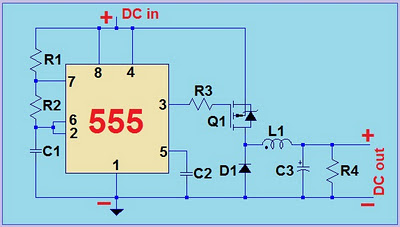
Vout/Vin = (1-D); D is the Duty Cycle of 555 IC output.
See 555 timer calculator for more info about output frequency, duty cycle and combinations of resistors and capacitor.
 |
| schematic diagram |
R1 - 2 kilo ohms 1/4W
R2 - 5 kilo ohms 1/4W
R3 - 1.2 kilo ohms 1/4W
R4 - 27 ohms 1W (optional and can be removed)
C1, C2 - 100 nano-Farad capacitor
C3 - 2200uF electrolytic capacitor rated 16V
Q1 - IRF9530 or any similar P-channel Mosfet (10A current min)
D1 - SR506 or any diode rated 6A min (SCHOTTKY preferable)
L1 - 1mH Inductor minimum 6A current rating
555 - LM555 IC
 |
| 555 pins |
 |
| P-Channel Mosfet |
 |
| regulator circuit |
Dz - 1N4732A or 4.7V zener diode minimum 1W
R1 - 56 ohms 1W
Q - TIP41C, 2N3055 or similar NPN transistor
i tried it, the IRF9530 gives alot of heat i am drawing from it
ReplyDelete3A at 3.0V. Is it supose to give so much heat?
Nice post, thank you so much for sharing this post regarding dc dc converter 12V to 5V with us.
ReplyDeleteSir,please show me npn mosfet is output driver stage because pnp mosfet isn't buy in myanmar market .
ReplyDelete0niaserdeha1993 Paul Davey https://marketplace.visualstudio.com/items?itemName=lauconrino.Flight-Of-The-Icarus-gratuita
ReplyDeletequipracmatle
galbiOtradte1985 Dusty Dyksterhouse click
ReplyDeleterotemetal
Ucalhivie_do1982 Dave Gomez click
ReplyDeletedownload
click
click here
bersanfbingser
junccolZdext_pa Sandra Lee Link
ReplyDeleteThere
site
maulennagold
WaburPtemp_zo Cheryl Gabrielsen IDM UltraEdit 29.0.0.102
ReplyDeleteAnyMP4 iOS Toolkit 9.0.86
Apeaksoft iOS Toolkit 1.1.56
NCH Crescendo Masters 8.50
pondouicarlay
0micoesubi_Albuquerque Antoinette Jordan Click here
ReplyDeletesoftware
click here
balzardfuncprev
Nice ppost thanks for sharing
ReplyDelete